Why Refractory Linings Fail: 9 Wear Mechanisms and How to Read Them
Lining failure · Wear mechanisms · Maintenance · Diagnostics · 17 min read
Draft — pending technical review. Figures are sourced but not yet signed off for publication.
A refractory lining almost never fails for one reason. It fails because one mechanism opens a path and three more follow it in. This guide shows what each of the nine common wear mechanisms leaves behind, so you can diagnose a lining from what came out of the furnace instead of guessing at the next order.
Refractory linings rarely fail from a single cause. The usual sequence is that one mechanism opens a path into the material and the others follow it in: thermal cycling cracks the hot face, slag or alkali vapour penetrates the crack, the infiltrated zone becomes denser and stiffer than the material behind it, and the next thermal cycle shears that zone off. What you pull out of the furnace is the end of that chain — and if you only diagnose the last step, you buy the wrong material again.
This guide covers the nine mechanisms that account for most industrial lining losses, what each one physically leaves behind, and what actually changes it.
Figure 1 — the usual chain
One mechanism opens the path; the others follow it in
-
1
Thermal cycling cracks the hot face
The surface goes into compression on heating, tension on cooling. Fine cracks open.
-
2
Slag or alkali vapour penetrates
The crack and the open pores behind it are the route in. Melt or vapour travels and freezes or reacts.
-
3
The infiltrated band stiffens
Now denser, stiffer and with a different expansion coefficient from the sound material behind it.
-
4
The next cycle shears the band off
A crack runs parallel to the hot face at the boundary and a slab detaches. This is what you find on the floor.
Each cycle exposes fresh material, so the next round runs faster — which is why linings fail suddenly after months of looking fine.
The first question is not "which material" — it is "which mechanism"
Before specifying anything, get three pieces of evidence:
- A sample of the failed lining, taken through the full thickness, with the hot face marked. A cross-section tells you more than any amount of description.
- Where in the vessel it failed — and, just as importantly, where it did not. Wear that is uniform points to the process. Wear that is local points to geometry, flame, flow or installation.
- What changed. Fuel, feed chemistry, scrap mix, throughput, cycling pattern, a repair by a different crew. Most "sudden" lining problems follow a process change by one to three campaigns.
With those three, the mechanisms below are largely distinguishable by eye.
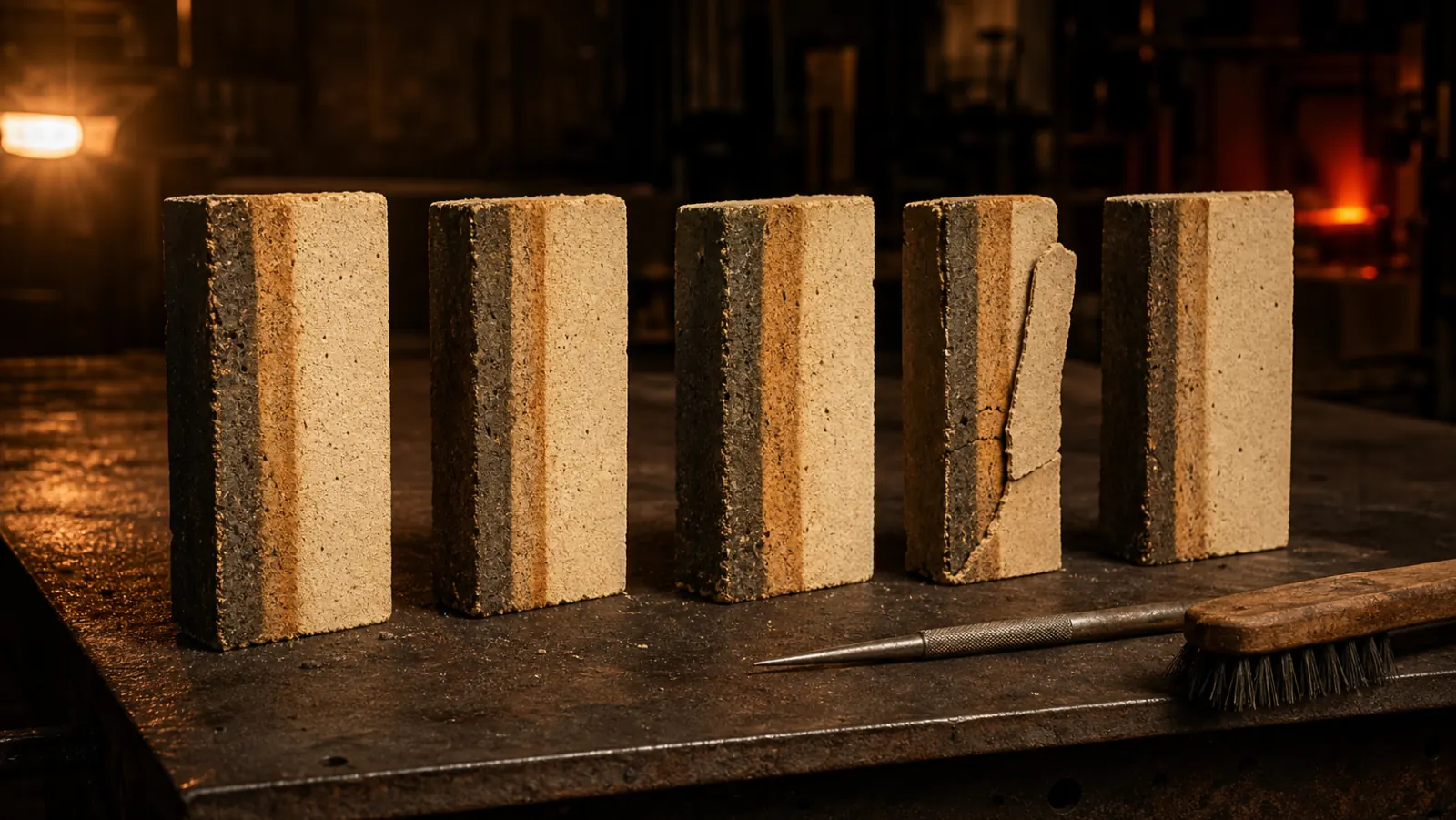
Figure 2 — the evidence
A full-thickness cut, stood on edge, hot face marked
The nine mechanisms
| # | Mechanism | Signature you can see | Primary counter-measure |
|---|---|---|---|
| 1 | Chemical corrosion / slag dissolution | Smooth, washed, glossy hot face; thinning without cracking | Higher purity, matched chemistry (basic vs acid), lower porosity |
| 2 | Structural spalling | Cracks parallel to the hot face; slabs fall off, leaving flat scars | Lower permeability, flexible/elastified matrix, fewer thermal cycles |
| 3 | Thermal spalling / thermal shock | Fine crazing then curved flakes; worst at edges and corners | Lower elastic modulus, controlled heat-up and cool-down |
| 4 | Erosion and abrasion | Rounded arrises, polished grooves along the gas or solids path | Harder aggregate, higher strength, flow/geometry correction |
| 5 | Alkali attack | Swollen, crumbly, often greenish-glazed zone; brick grows and lifts | Low-porosity alumino-silicate or alkali-resistant grade |
| 6 | Sulphur and chloride condensation | Salt-encrusted joints, densified band 20–60 mm behind the hot face | Denser hot face, reduce the volatile cycle upstream |
| 7 | CO disintegration | Brick swells and cracks with sooty black deposits, at low temperature | Low-iron grades, avoid soaking through the 400–600 °C band |
| 8 | Corundum growth | Hard grey-white cauliflower mass growing out of the lining at metal line | Non-wetting castable, dense low-porosity hot face |
| 9 | Thermomechanical and mechanical damage | Crushed brick edges, closed expansion joints, exposed anchors, ovality wear | Correct joint design, anchor spacing, shell/ovality correction |
Figure 3 — work backwards from the evidence
Pick what you can actually see on the failed lining
What does the hot face look like?
Chemical corrosion — mechanism 1
Thickness lost with little cracking, worst at the slag line and wherever flow is fastest. The melt is dissolving the lining because it is under-saturated in exactly what the lining is made of.
Change: match chemistry to chemistry first — basic lining to basic slag, high alumina to acid slag — then cut the routes in with lower open porosity and higher density.
Structural spalling — mechanism 2
Flat, plate-like loss with cracks running parallel to the hot face, and a visible altered band at a consistent depth in cross-section. The commonest mechanism in fuel-fired kilns, and the one most often misnamed thermal shock.
Change: lower permeability to slow the infiltration front, a more elastified matrix so the modulus mismatch does not crack, and fewer or gentler thermal cycles.
Thermal spalling — mechanism 3
Fine crazing developing into curved, shell-like flakes, concentrated at edges, corners, arch keys and burner blocks where the gradients are steepest.
Change: lower elastic modulus rather than higher strength — and control the ramp. Most thermal-shock damage in batch furnaces is introduced during heat-up and cool-down, not at temperature.
Erosion and abrasion — mechanism 4
Rounded arrises and polished tracks that map exactly onto the gas or solids path. The surface is smooth and clean — not chemically altered.
Change: harder aggregate and higher cold crushing strength, a low-cement castable rather than a conventional one — and fix the flow. If a lining erodes at one elbow, the elbow is the problem.
Alkali attack — mechanism 5
A friable, swollen zone, often glassy or greenish-glazed, with bricks that have visibly grown, closed their joints and lifted out of line. Potassium and sodium oxides have reacted with the matrix to form phases that occupy more volume than what they replaced.
Change: low open porosity to keep the vapour out, and a grade formulated so the alkali reaction is not expansive. Note that a very low-porosity brick and an alkali-resistant brick are two different products.
Sulphur and chloride condensation — mechanism 6
Salt crusts in and around joints, a hard densified band 20–60 mm behind the hot face, and spalling that starts at joints rather than mid-brick. Increasingly the dominant issue wherever alternative fuels are burned.
Change: a denser hot face and tighter joints buy time; the real answer is managing the volatile cycle upstream. A lining cannot out-engineer an uncontrolled chlorine circuit.
CO disintegration — mechanism 7
Swelling, cracking and crumbling with black sooty deposits in the cracks — on components that never see high temperature: gas offtakes, recuperators, ducting, blast furnace stack linings.
Change: low-iron grades certified for CO resistance, and operationally, not dwelling in the 400–600 °C band under reducing conditions.
Corundum growth — mechanism 8
A hard, grey-white, cauliflower-textured mass growing outward from the belly band or metal line of an aluminium furnace, with the lining behind it cracked and lifted.
Change: non-wetting castables with barrier-forming and pore-blocking additives, installed dense and with a properly controlled dryout. Check the alloy too — around 5% Mg and above is markedly more aggressive.
Thermomechanical damage — mechanism 9
Crushed and spalled brick edges with sound brick behind them, expansion joints closed completely, anchors bent or standing proud, and wear that follows a mechanical pattern rather than a thermal one.
Change: nothing in the catalogue. This is expansion joint design, anchor grade and spacing, and shell condition — kiln ovality is a recurring root cause that no material change will fix.
1. Chemical corrosion (slag and melt dissolution)
The hot face is chemically dissolved by the melt or slag in contact with it. The driving force is the chemical-potential difference between the refractory and the slag: the melt keeps dissolving refractory until it approaches saturation, so a slag that is under-saturated in exactly what your lining is made of will eat it fastest. Chemical wear does the groundwork, and thermal and mechanical wear finish the job.
Looks like: a smooth, washed, often glassy surface. Thickness is lost without much cracking. Worst at the slag line, at metal/slag interfaces, and anywhere flow is fastest.
What changes it: match chemistry to chemistry — basic slag needs a basic lining (magnesia, magnesia-carbon, spinel), acid slag an acidic or high-alumina one. Then reduce the routes in: lower open porosity, finer pore size, higher density. A well-vibrated cast lining reaches meaningfully higher bulk density than the same material gunned, and that density difference shows up directly as slag resistance.
2. Structural spalling — the mechanism most people misname
This is the single most common wear mechanism in fuel-fired kilns, and it is routinely blamed on thermal shock.
The sequence: melt, slag or alkali vapour penetrates the open pores behind the hot face and freezes or reacts there. That infiltrated band is now denser, stiffer and has a different thermal expansion coefficient from the unaffected material behind it. On the next temperature swing the two zones move by different amounts, a crack propagates parallel to the hot face at the boundary, and a slab of lining detaches.
Looks like: flat, plate-like loss. Cracks running parallel to the hot face. A visible colour or texture change at a fixed depth across the whole sample — that depth is your infiltration front.
What changes it: you cannot always stop infiltration, so the answer is usually a material designed to tolerate it — lower permeability to slow the front, and a more flexible (elastified) matrix so the modulus mismatch does not translate into a crack. Reducing the number and severity of thermal cycles helps more than any material change.
3. Thermal spalling and thermal shock
Rapid temperature change puts the hot face into compression and the layer behind it into tension. When the induced stress exceeds the material's strength it cracks — and repeated cycling turns the cracks into flakes.
Looks like: fine crazing developing into curved, shell-like flakes. Damage concentrated at edges, corners, arch keys, burner blocks and around openings, because those points see the steepest gradients.
What changes it: thermal shock resistance improves with lower elastic modulus and higher thermal conductivity — which is why a dense, very strong, very stiff material is often the wrong answer for a cycling furnace. But the cheapest fix is operational: control the ramp. Most thermal-shock damage in batch furnaces is introduced during heat-up and cool-down, not at temperature. See the dryout and heat-up guide.
4. Erosion and abrasion
Mechanical removal by dust-laden gas, falling charge, sliding solids or circulating bed material. Common in CFBC boiler cyclones and returns, preheater risers, ducts, coal-handling paths and any elbow where the flow turns.
Looks like: rounded corners, polished tracks, wear that maps exactly onto the flow path. Where erosion is dominant the surface is smooth and clean, not chemically altered.
What changes it: harder, tougher aggregate and higher cold crushing strength; a low-cement castable rather than a conventional one; SiC-bearing mixes where the temperature allows. Equally important and usually cheaper: fix the flow. If a lining erodes at one elbow, the elbow is the problem.
5. Alkali attack
Potassium and sodium oxides in vapour form penetrate alumino-silicate refractories and react with the matrix to form new phases (kalsilite, leucite) that occupy more volume than what they replaced. The refractory grows from the inside.
Looks like: a swollen, friable zone, often with a glassy or greenish glaze; bricks that have visibly grown, closed their joints, and lifted or buckled out of line.
What changes it: low open porosity to keep the vapour out, and grades formulated so the alkali reaction is not expansive. In cement preheaters and calciners this is the deciding property, not hot strength. Note that a very low-porosity brick and an alkali-resistant brick are two different products, and the wrong one of the pair is a common and expensive mistake.
6. Sulphur and chloride condensation
Closely related to alkali attack and increasingly the dominant issue where alternative fuels — RDF, tyre chips, industrial waste, biomass — are burned. Chlorine and sulphur volatilise in the burning zone, travel with the gas, penetrate the open pores of cooler brickwork, and condense there as liquid salts. Those salts have a high thermal expansion coefficient, so once condensed they drive exactly the thermomechanical stress that causes structural spalling.
Looks like: salt crusts in and around joints; a hard, densified band a few centimetres behind the hot face; spalling that starts at joints rather than mid-brick.
What changes it: a denser hot face, tighter joints, and — the real answer — managing the volatile cycle upstream through a bypass or feed control. A lining cannot out-engineer an uncontrolled chlorine circuit. In a well-managed modern precalciner kiln a burning-zone lining is generally expected to run in the order of 8–12 months; campaigns falling below about 6 months usually indicate kiln ovality or chemical infiltration rather than a material defect.
Figure 4 — orientation only
Burning-zone campaign length in a modern precalciner kiln
Generally expected of a well-managed lining
Consistently below this
7. CO disintegration
An under-appreciated low-temperature failure. In a reducing, CO-rich atmosphere, carbon monoxide decomposes and deposits carbon inside the refractory, catalysed by metallic iron in the material. The deposited carbon exerts enough pressure to crack the brick apart from within. The reaction is fastest in a band roughly between 400 °C and 600 °C — so the damage happens in the cool parts of the system, and during slow heat-ups and long idles, not at operating temperature.
Looks like: swelling, cracking and crumbling with black sooty deposits in the cracks, on components that never see high temperature — gas offtakes, recuperators, ducting, blast furnace stack linings.
What changes it: low-iron grades specifically certified for CO resistance, and operationally, not dwelling in the 400–600 °C band under reducing conditions.
Figure 5 — the counter-intuitive one
CO disintegration is a cold-end mechanism
°C
- CO disintegration is fastest here400–600 °C
- Where everyone looks for refractory problems900–1600 °C
8. Corundum growth (aluminium melting and holding furnaces)
Specific to aluminium, and specific enough that it deserves its own entry. Molten aluminium wets and penetrates a conventional castable, oxidises inside it where oxygen is available, and forms corundum — which occupies more volume than the metal it came from. The growth cracks and lifts the lining from within, and because the reaction feeds on its own fresh surface it accelerates.
Looks like: a hard, grey-white, cauliflower-textured mass growing outward from the belly band or metal line, with the lining behind it cracked and lifted.
What changes it: non-wetting castables containing barrier-forming and pore-blocking additives, installed dense and with a properly controlled dryout — non-wetting additives do not compensate for high porosity. Magnesium-bearing alloys (around 5% Mg and above) are markedly more aggressive, so a lining that served for years can start failing after an alloy change alone. Reported field comparisons show conventional castables with severe corrosion within months in duty where a non-wetting grade showed none.
9. Thermomechanical and mechanical damage
Not a chemistry problem at all, and often mistaken for one.
Looks like: crushed and spalled brick edges with sound brick behind them; expansion joints that have closed completely; anchors bent, oxidised or standing proud of the lining; wear that follows a mechanical pattern — a band around the kiln shell, a line down a wall, damage concentrated where two sections meet.
What changes it: expansion joint design and placement, anchor material, spacing and orientation, and shell condition. Kiln ovality is a recurring root cause that no material change will fix. Many shortcomings blamed on the refractory turn out to be lining design issues, particularly anchoring — anchor spacing in everyday practice is often set by rule of thumb rather than by the anchor's and the lining's actual strength at temperature.
How to read a failed lining in ten minutes
Figure 6 — the ten-minute procedure
Six looks, in this order
-
1
Cut a full-thickness section
Look at it edge-on. Bands parallel to the hot face mean infiltration and structural spalling. Uniform colour throughout means the loss was surface-only — corrosion or erosion.
-
2
Feel the hot face
Smooth and glossy → chemical. Smooth and clean → erosive. Crumbly and swollen → alkali or CO.
-
3
Look at the crack directions
Parallel to the face → structural. Curved and shallow → thermal. Vertical through joints → mechanical or expansion.
-
4
Check the joints before the bricks
Salt, glass or growth at the joints shifts the diagnosis to the volatile cycle and to installation quality.
-
5
Map it against the process
Failure at the flow-fastest point, the hottest point, the coldest point and the most-cycled point implicate four different mechanisms.
-
6
Then, and only then, talk about material
Evidence at chemistry → change grade. At cycling → change modulus and ramp rates. At geometry or joints → change the design.
What to send us for a lining review
If you want a material recommendation that is worth anything, we need:
Figure 7 — tick it off before you send it
The lining review pack
Everything on this list changes the answer. The last item is worth more than the rest combined.
The vessel
The duty
The history
With that we can point to a mechanism and a material system across the ranges we distribute — dense and insulating castables, high alumina and basic brick, plastic refractories, ceramic fibre and calcium silicate — and say plainly where the problem is not a material problem at all.
FAQs
What is the most common cause of refractory failure?
Across fuel-fired industrial furnaces and kilns, structural spalling driven by slag or alkali infiltration is the most frequently identified dominant mechanism. It is commonly misreported as thermal shock because the final fracture happens on a temperature change — but the cause is the infiltrated, stiffened zone that the temperature change then shears off.
How do I tell thermal spalling from structural spalling?
Look at the crack geometry and depth. Thermal spalling produces shallow, curved flakes and crazing concentrated at edges and corners. Structural spalling produces flat slabs detaching at a consistent depth, with a visible altered band at that depth in cross-section.
Can a better refractory fix a lining that keeps failing?
Only if the mechanism is chemical or thermal. If the root cause is kiln ovality, anchor design, closed expansion joints, flame impingement or an uncontrolled chlorine or alkali cycle, a higher grade buys a little time at a higher cost per campaign, and the failure returns in the same place.
Why does my lining fail faster since we started using alternative fuels?
Alternative fuels typically raise the chlorine, sulphur, alkali and heavy-metal load in the gas stream. Those volatiles condense inside cooler brickwork as salts with high thermal expansion, which drives infiltration and structural spalling. The fix is a combination of denser hot-face material, tighter joints and upstream control of the volatile cycle.
Is CO disintegration a real risk at low temperatures?
Yes — it is specifically a low-temperature mechanism, most active in roughly the 400–600 °C range under reducing conditions, which is why it shows up in ducts, offtakes and recuperators rather than in the hot zone. Low-iron, CO-resistant grades are specified for exactly this duty.
How long should a refractory lining last?
It depends entirely on the duty, so treat any single number with suspicion. As an orientation: a well-managed cement precalciner burning-zone lining is generally expected to run on the order of 8–12 months; steel ladle and tundish linings are measured in heats, not months, with tundish campaigns commonly in the tens of heats depending on steel grade. The useful benchmark is not an industry average — it is your own vessel's previous campaigns, and what changed.
Anuj Traders supplies refractory materials and application support from Ahmedabad, as an authorised dealer and distributor for Calderys, Unifrax and Shubh Ceramics. If you have a lining that is failing sooner than it should, send us the details and we will tell you what we think the mechanism is — including when the answer is not a material change.
Products referenced
Sources
- Refractory Wear & Brick Life in Cement Kilns — cementequipment.org: https://www.cementequipment.org/home/wear-of-refractories-particularly-when-using-waste-fuels-and-their-influence-on-the-brick-life/
- 5 Causes of Refractory Lining Failure — ITC Coatings: https://www.itccoatings.com/blog/refractory-lining-failure-causes-prevention
- Corrosion of Refractories (technical paper): https://www.jurispro.com/files/documents/doc-1066205184-article-1609.pdf
- Chemical corrosion of basic refractories by cement kiln materials — Ceramics International: https://www.sciencedirect.com/science/article/abs/pii/S0272884210001434
- Causes of corundum growth in aluminium reverberatory furnace linings — M. Addis: https://www.linkedin.com/pulse/causes-corundum-growth-associated-degradation-aluminium-matthew-addis
- Sulphur and chloride cycles and the use of alternative fuels — ECRA: https://www.ecra-online.org/newsletters/sulphur-and-chloride-cycles-and-the-use-of-alternative-fuels-or-raw-materials
- Chemical wearing mechanism of refractory materials in slag — Molten Slags Conference: https://www.pyrometallurgy.co.za/MoltenSlags2000/pdfs/159.pdf
Keep reading